Abstract
Space-based solar technology (SBSP) is a potentially revolutionary technology that aims to capture and transmit solar energy from space. By enabling all-weather transmission of nearly unlimited power from space, it is a technology that, if successfully developed, has far-reaching consequences and may even eliminate energy scarcity. While there have been numerous attempts at developing SBSP, and space-based prototypes have already been successfully deployed, the technology has remained proprietary and largely inaccessible to the public. Project Elara is a not-for-profit initiative that aims to develop the world’s first fully open-source SBSP system for the sole purpose of delivering universal energy around the world. The following report describes the technical progress of the Project within the year, the limitations and challenges it faces, and its planned future work.
Introduction
Space-based solar power (SBSP) has been an elusive dream for decades, but its revolutionary potential has been hindered by many technical and practical challenges. Over the course of a year, Project Elara has developed a concept design for an SBSP system that, to our knowledge, is completely novel in the field. Unlike traditional designs, which typically rely on phased arrays, this design relies on tunable free-electron masers that produce highly-collimated beams. This leads to increased efficiency in power-beaming and a much narrower bandwidth to avoid interference with common telecommunications frequencies. Additionally, solar mirrors are used to collect sunlight, avoiding the complexity and fragility of solar panels, and their non-rigid nature allows mass deployment, maximizing solar collection area. A small-scale technology for a proof of the technical feasibility of the concept reached an advanced stage of development, and is planned for construction and testing in the following year. Challenges, however, still remain regarding theoretical uncertainties around certain design parameters. A physical prototype is planned to be built in the near future to provide experimental confirmation of the concept.
Technological overview
A novel design concept for an SBSP system was developed throughout the course of the year. The system is composed of the following components:
A solar mirror in geostationary orbit, which focuses solar energy into a highly-concentrated beam
A solar-pumped free-electron maser, which converts the concentrated solar beam into microwaves
A series of terrestrial receivers to receive the delivered energy on Earth
A composite parabolic reflector design was chosen for the solar mirror, due to its proven capabilities in producing concentrated solar energy in solar furnaces[1] and in the successful past deployments of large mirrors in space[2]. The reflector is composed of small, flexible segments, which can be folded during launch and deployed to their full size in orbit. Autonomous lock mechanisms would allow the individual segments to join together into one, as shown in Figure 1. Large power collection areas can be achieved in this manner, without the need to launch the mirror in one piece, which would require unrealistically large payload bays.
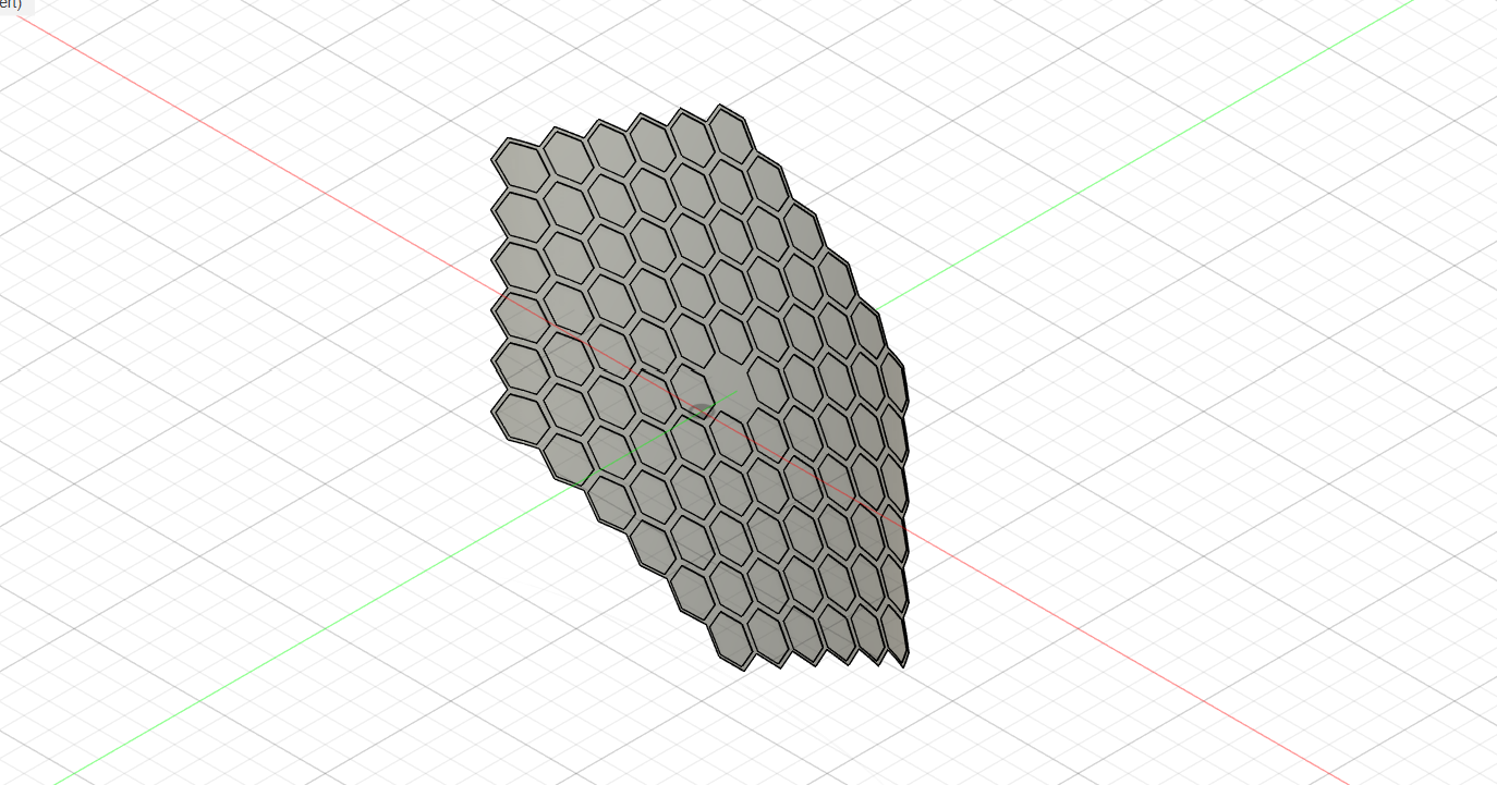
Figure 1:CAD model of spacecraft solar mirror
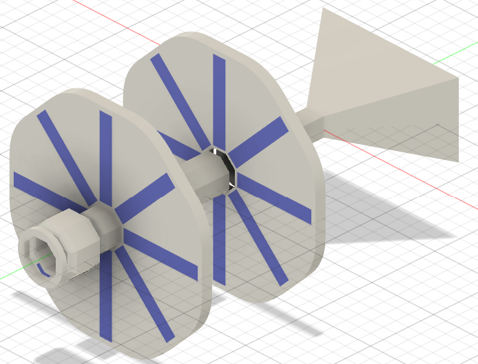
The beam power is then fed into a free-electron maser, as shown in Figure 2. A photon-enhanced thermionic emission (PETE) cathode is utilized as an electron source, combining photoelectric and thermionic emission to maximize efficiency, improving efficiency beyond the highest experimentally-achieved thermionic efficiencies of around 25% Yarygin, 2012. PETE has been theoretically speculated to be capable of achieving up to 70% efficiency Segev et al., 2015, although this has not been experimentally proven. In principle, it may be possible to achieve even higher efficiencies, since the thermionic efficiency is not subject to the Shockley-Queisser limit for photovoltaic panels, which constrains maximum efficiencies of around 33% Rühle, 2016. Instead, its theoretical efficiency is capped by the Carnot limit Granet et al., 2020; assuming the cold anode is shielded from the Sun, it may be able to reach temperatures as low as [3], which can be further reduced by cryogenic cooling prior to launch. With a hot cathode operating temperature of , the Carnot limit predicts an efficiency of close to 96%, far above that of conventional solar panels.
The free-electron maser utilizes electrostatic acceleration via a potential difference in the kV range, with the prototype design targeting a potential difference of . While much lower than conventional free-electron lasers, prior experiments have already indicated the feasibility of such a design Drori et al., 1996. Electrets or thermoelectric generators are proposed as minimum-energy-consumption sources to maintain the potential difference, with the latter taking advantage of the high temperatures of the hot cathode as a natural heat source. A selection of various materials for the hot cathode from Turner, 1976 is shown in Table 1; the precise choice of cathode material will be determined in future research, based on sustainability and efficiency.
Table 1:Table of characteristics for common thermocathode materials. From Turner, 1976.
| Material | Operating temperature | Emission efficacy () |
|---|---|---|
| Pure tungsten | 2500 K | 5 mA/W |
| Thoriated tungsten | 2000 K | 100 mA/W |
| Barium aluminate | 1300 K | 400 mA/W |
| Oxide-coated[4] | 1000 K | 500 mA/W |
Taking advantage of the natural vacuum of space, no artificial vacuum chamber is necessary for free-electron maser operation, avoiding the material costs and high energy consumption required to maintain vacuum within conventional free-electron masers (cite source) and the need for fragile glass to surround electron guns. Meanwhile, the stream of ejected electrons is collimated via a pair of sextupole magnets, as shown in Figure 2. Afterwards, guiding magnets are utilized to create the electron beam and feed it into the undulator, as shown in Figure 3.
The undulator is cylindrical in shape and primarily constructed out of lightweight microwave-transparent materials, which can easily be 3D printed, enabling mass manufacturing. PETG was selected as the prototype material due to its stability, low thermal conductivity, and low density, minimizing launch weight. However, several issues were identified with PETG; notably, its moisture sensitivity, which may lead to outgassing under vacuum without pre-drying. A 24-hour vacuum bake at for each solid part (containing a volume of around ) was suggested improve stability and performance in high vacuum, though it is likely that an alternative material must be used for ultra-high vacuum (UHV) maser operation.

Figure 2:The prototype free-electron maser design. Note that a photocathode is planned to be used for the initial prototype, with PETE used in the full-scale maser.
The undulator cavity is of the Fabry–Pérot design, with two mirrors at either end of the cavity to amplify synchrotron radiation emitted by the electron beam. However, hole coupling is used instead of transmissive coupling, due to its simplicity and proven use in free-electron lasers in the infrared regime Varro, 2012. An anti-reflective coating is applied to the output coupler, along with an adjustable iris aperture to achieve resonance and ensure coherent amplification of microwave radiation. Slotted magnets are placed at adjustable heights, allowing the magnetic field within the undulator to be adjusted. A CAD model of the prototype design is shown Figure 3. While not incorporated in the initial design, work is planned on incorporating beam energy recovery and electron recycling, mitigating the energy losses and eventual degradation of the hot cathode.
(a)CAD model of electron gun
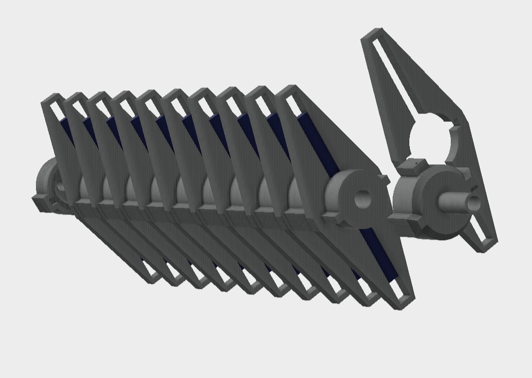
(b)CAD model of undulator
Figure 3:CAD models of concept free-electron maser
The tunable nature of a free-electron maser is a major advantage over other maser designs, as the beam wavelength can be adjusted to optimize for power efficiency. The design primarily focuses on the L-band and S-band range of , due to minimal power loss due to atmospheric attenuation at these frequencies (Ippolito (1981)Kocifaj et al. (2021)ITU-R (2022)Ho et al. (2007)). However, power loss due to beam divergence is non-negligible even for highly-coherent light sources, particularly for beaming from geostationary orbit Bridges, 1975. Due to the diffraction limit, the beam divergence angle , where is the laser aperture. For small apertures, this leads to beam spreading of well over 30 km at the Earth’s surface, causing the beam to lose collimation entirely. To counter this issue, a novel technique has been developed, which we term coherent beam synthesis. By superimposing two (or more) maser beams, the interference between the two beams produces a new synthesized beam. The synthesized beam has a divergence of , which is independent of the apertures of each individual beam. The calculated beam diameter on Earth’s surface is then given by . Computed values are given in Table 2.
Table 2:Beam diameter on the ground for L-band and S-band microwave beams (under ideal conditions)
| Frequency | Beam diameter |
|---|---|
| 1 GHz | 4.6 km |
| 2 GHz | 3.3 km |
| 2.5 GHz | 2.9 km |
| 3 GHz | 2.7 km |
The resulting beam widths are within the size of conventional solar power installations, though it is possible to capture only part of the beam (for instance, with a football-field-sized receiver array) for powering communities with lower energy utilization. Proposed terrestrial receivers include a variety of designs, as shown in Table 3, serving communities from single buildings (such as clinics or hospitals) to metropolitan areas and even larger populations.
Table 3:Proposed ground receiver designs at different scales
| Receiver | Use case |
|---|---|
| Converted oil rigs | Extremely large power arrays, mounted off the coast and away from population centers, capable of powering entire regions |
| Power fields | Large multi-kilometer power arrays for providing power to a metropolitan area |
| Dual-use telecommunications arrays | Upgrading existing infrastructure to simultaneously receive power |
| Ship-bound/barge-based arrays | Quick deployment to coastal regions and for power provision in disaster regions close to the coast |
| Tower-suspended arrays | Redistributing power to remote regions |
| Small receivers | Providing power to individual communities or for emergency/humanitarian workers |
The spacecraft design consists of a large primary mirror, a small secondary mirror, and a satellite bus that contains the free-electron maser and supporting equipment. As shown in Figure 4, the spacecraft is angled to continuously face the Sun throughout its orbit, enabling 24-hour power collection. The design envisions a constellation of power satellites, beaming power around the world. During the brief period of time the Earth passes through the ecliptic, other satellites in the constellation can provide power, ensuring that power is always supplied.

Figure 4:Showcase of satellite orbital arrangement. The orbit is designed to ensure the spacecraft is always Sun-facing.
While geostationary orbit has negligible atmospheric drag, station-keeping is still necessary to avoid orbital decay due to other effects, such as radiation pressure. Methods proposed include electrodynamic tethers and magnetically suspended reaction wheels, although further research is necessary to determine a satisfactory solution. In addition, the high Delta-v required for geostationary orbit insertion requires minimizing spacecraft weight. Various launch sites were proposed as possible options, as shown in Table 4.
Table 4:Considered launch sites and facilities
| Launch site | Remarks |
|---|---|
| Mid-Atlantic Regional Spaceport | Already used in operation by Firefly/RocketLab |
| Barge-based launch (in the Mediterranean, Sargasso Sea, Bay Area, or other calm shallow sea) | A proven concept, as shown by Sea Launch |
| Launch from islands or atolls, such as Omelek/Wallops Island | Historically has been a launch site for university-sponsored space vehicles |
| Building a new launch site on an uninhabited island or lagoon | Most customizable, though logistical and financial challenges are difficult to overcome |
An open-source microcontroller code based on the ARM Cortex-M architecture was developed as a proof-of-concept for the spacecraft’s on-board computer (OBC)[5]. This architecture was chosen as it has already been successfully deployed on spacecraft Ozer, 2010. A rudimentary outline of the basic satellite systems, including communications, is shown in Figure 5. The construction of a small-scale technology demonstrator in the following year will be essential to demonstrating the viability of the concept.
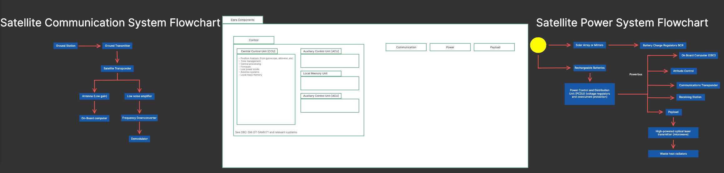
Figure 5:Satellite systems for the proposed power satellite
Methods
A combination of CAD, analytical methods and numerical analysis was utilized in the process of developing the concept. As the concept was intended to culminate in a buildable prototype, 3D models of the system were made in CAD software, including the space mirror and scaled-down versions of the electron gun and undulator. While models initially utilized proprietary software, the models were exported to the STEP open format to ensure broad compatibility, including with open-source CAD software.
Meanwhile, coherent beam synthesis and electron beam propagation calculations in the undulator were done analytically. The far-field approximation for the beam profile of the combined beam was found to be:
Where and are the Gaussian beam width and radius of curvature,respectively. The minima of the central lobe of the pattern (as shown in Figure 5) are located at , leading to a beam diameter given by:
From the above, the results for the beam width across the L-band and S-band were obtained, as in equation (cite the equation where we provide beam width estimates for 1 GHz, 2 GHz, and 2.5 GHz). The result is only applicable in the far field, leading to a difference between the numerically-evaluated superposition of the two beams and the analytical calculation, as is clear from Figure 6. However, the far-field approximation is more than adequate when considering beam propagation from geostationary orbit.
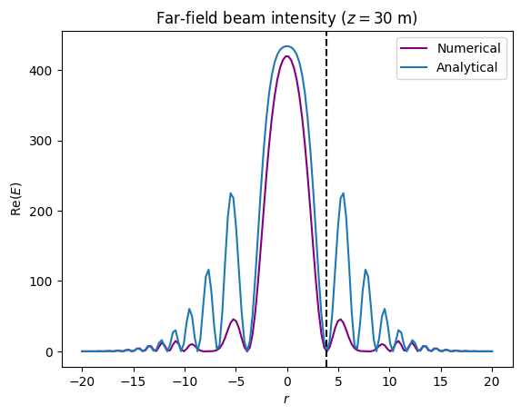
(a)Far-field synthesized beam at 30 m
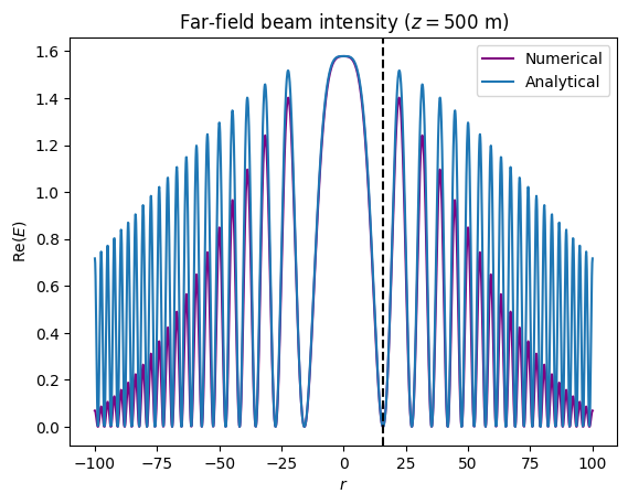
(b)Far-field synthesized beam at 500 m
Meanwhile, electron trajectories through the undulator were computed numerically[7]. The OSCARS software Brookhaven National Laboratory, 2018 was initially used for beam-tracing. Simulations were done with beam energies of and magnetic field strengths of , as shown in Figure 7 and Figure 8. However, OSCARS produced null results below a beam energy of . It was not possible to determine whether this was due to physical reasons or (more likely) a software limitation of the integrator; as OSCARS was designed for simulating beam energies around the MeV to GeV scale, it is not unfeasible that it simply cannot accurately simulate lower-energy beams.
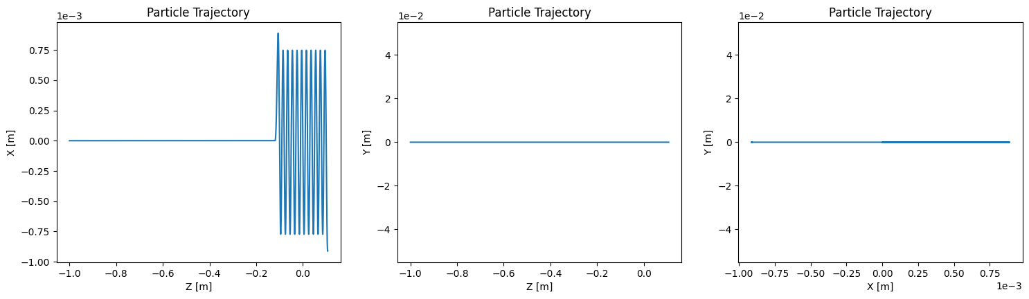
Figure 7:520 keV beam simulated with OSCARS (2D view)
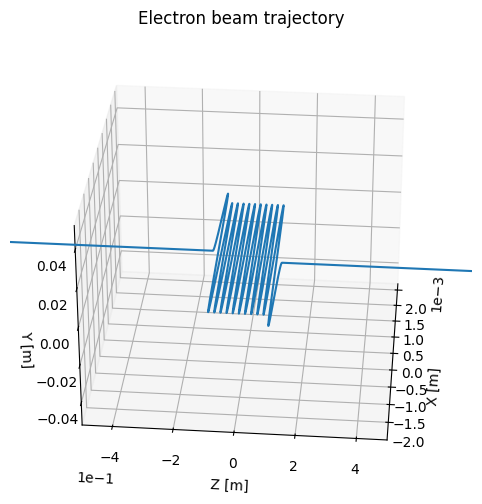
Figure 8:520 keV beam simulated with OSCARS (3D view)
For simulations of lower-energy beams, a second-order leapfrog integrator was used for beam tracing[8]. The leapfrog integrator was validated on a test problem with a uniform magnetic field , as shown in Figure 9.
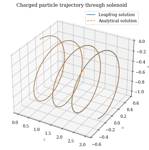
Figure 9:Leapfrog numerical solution for a particle under a uniform field, with step size of
Afterwards, the integrator was used to simulate the propagation of an electron beam through an undulator, whose magnetic field was assumed to take the following form:
Where is the maximal field strength of the dipole magnets, , is the undulator period, and is the axial field strength, and where the maser wavelength is given by Schmüser et al., 2014:
Where is the magnitude of the elementary charge, is the electron mass, and is the speed of light. The presence of the axial field serves to stabilize the beam and avoid beam divergence Drori et al., 1996. In the case it is possible to obtain an approximate analytical solution in the form Schmüser et al., 2014:
Where it is evident that is the maximum beam displacement. However, the exact solution generally cannot be found by analytical means. Instead, numerical simulations were used to integrate the Lorentz force equations for the undulator magnetic field, given by:
Where was a small smoothing factor added for numerical stability, and recovers the physical form of the Lorentz force. To avoid numerical overflows, it was assumed that , and thus the simulations provided only qualitative results (the provided values of should be understood to be parameters within these initial simulations, not physical velocities). Two simulations with zero axial field are shown in Figure 10 and Figure 11, while a third simulation with an axial field of is shown in Figure 12. It can be seen that of the two simulations of zero axial field, the former (with ) performed better than the latter (with ); in general, simulations revealed that higher-energy beams were more stable (less subject to divergence) than lower-energy beams.

Figure 10:Solution of dimensional Lorentz force equations with and initial velocity . Velocities are not physical and for reference purposes only.

Figure 11:Solution of dimensional Lorentz force equations with and initial velocity . Velocities are not physical and for reference purposes only.

Figure 12:Figure 9: Solution of dimensional Lorentz force equations with and , with added axial field. Velocities are not physical and for reference purposes only.
To obtain quantitative results, additional simulations were performed utilizing a nondimensionalized form of the Lorentz force equations, given by:
Where the phase-space variables are defined in relation to the physical positions and velocities , via:
The results of the simulation are shown in Figure 13 and Figure 14, and yielded promising results for values of , , and . In particular, the characteristic sinusoidal trajectory resembles the analytical result given by equation (5), suggesting strong agreement with the theoretical result. The oscillating “wiggling” trajectory is essential for the coherent emission of microwave radiation in a free-electron maser, and the surprising result that this is possible at (corresponding to about 2.2 keV in terms of beam energy) allows the development of a “tabletop device”, unlike the typical beam energies in the hundreds or even thousands of kilovolts.

Figure 13:Simulation results for nondimensionalized Lorentz force equations at (2D view)
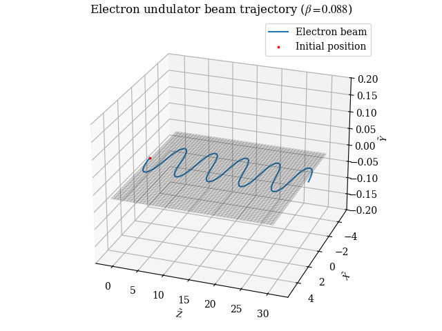
Figure 14:Simulation results for nondimensionalized Lorentz force equations at (3D view)
However, confirmation was still required to establish that its results were indeed correct. Thus, a final validation test was performed using a different nondimensionalized form of the Lorentz force equations, given by:
Where , , and , and where , . For additional verification, the simulations were done using SciPy’s native solve_ivp solver instead of the leapfrog integrator. The results of the simulation are shown in Figure 15. However, the SciPy integrator both failed to reproduce the low-energy solution from the leapfrog integrator (Figure 14) and the high-energy solution from OSCARS (Figure 8), and was also unable to reproduce the analytical solution given in (5). Thus, it is clear that more work will be needed before a satisfactory numerical treatment of the problem is complete.

Figure 15:Simulation results with SciPy-based solver
Discussion
While simulation results did not challenge the theoretical soundness of the design, they disagreed on the beam energy required for the free-electron maser. Estimates of the minimum beam energy are given in Table 5, based on simulation results as well as theoretical considerations[9], though they range wildly. The few points of agreement among the different simulations included the finding that a weaker magnetic field strength was advantageous, as it would be less likely to perturb electron trajectories significantly and possibly even drive the electron beam backwards. Additionally, the presence of an axial field could avoid beam divergence, as evidenced in Figures 8b and 9, where the application of an axial field yielded a far more stable beam, despite similar parameters otherwise. To partially compensate for the uncertainty around the parameters, the prototype design incorporated a tunable magnetic field and electrostatic potential, meaning that the design could be experimentally tuned to obtain the desired beam energies.
Table 5:Minimum beam energy estimates from numerical simulations and theoretical predictions
| Data source | Minimum beam energy |
|---|---|
| OSCARS simulations | ~520 keV |
| Leapfrog integrator simulations | ~2 keV |
| Theoretical beam radius condition () | ~100 keV (OSCARS estimate) |
| Theoretical beam displacement condition () | Essentially unconstrained |
Other areas of development were far more positive, including the indications that beam synthesis could drastically reduce beam divergence to acceptable levels, and optimistic estimates of power efficiency, although it remains to be seen if both can be realized in practice. In addition, there are major unknowns in implementing the concept design in practice, including whether the materials used can withstand vacuum conditions. It is expected that these questions can be more satisfactorily answered in the 2026 research season, when planned experiments for coherent beam synthesis and prototype testing is expected to begin.
Conclusion
Over the course of a year, Project Elara has independently developed a fully-open-source design for a space-based solar power system. The elements of the design, including the solar mirror, free-electron maser, and terrestrial receivers, were developed and analyzed. Digital models of an implementable prototype were designed, and preparatory systems development for future space hardware was begun. Numerical simulations for the free-electron maser were conducted to establish parameters for the system, which were ultimately inconclusive. Future work will involve further advances in laser/maser modelling, and numerical simulations and the development of a physical prototype to prove the viability of the concept.
Disclosures
We disclose that Generative AI (GenAI) was used in the course of the research. Use of GenAI technologies was limited to literature search, brainstorming, and validation purposes. All content presented herein is original work. For more information, please see Project Elara’s AI content archive.
Content re-use
The presented CAD models, as well as renders of the CAD models (Figures 1, 2a, 3), are under the MIT license and can be found in Project Elara’s laser research repository. The spacecraft OBC code and system design (as shown in Figure 5) are also under the MIT license and can be found in Project Elara’s spacecraft development repository. All other content in this paper is dedicated to the public domain and has no restrictions on use.
Acknowledgments
This work was supported by the Rensselaer Center for Open Source (RCOS), to whom we are deeply grateful. In addition, we also thank Professor Wilke for her advice regarding experimental testing of coherent beam synthesis, Professor N’Gom for his advice on experimental optics, and both Professor Persans and Professor Nanou for their continuous support. Lastly, we would like to thank all of our friends and mentors, without whom this research would not be possible.
For instance, the solar furnace at Odeillo. See https://
www .promes .cnrs .fr/ From Plante & Lee, 2005. Assuming geostationary orbit, the temperature figure given is -196 Celsius when facing away from the Sun, translating to 77 K.
For instance, a nickel cathode with barium oxide coating
Source code is available in the Elara spacecraft repository.
Analytical calculations are approximate and thus do not fully correspond to the numerical (exact) solution. The black dashed line gives , the radius of the central lobe.
The polarity of the electron’s charge was not taken into account, as the equivalent results may be obtained by reversing the magnets.
The leapfrog method used is similar in some respects to numerical integrators used for particle-in-cell (PIC) methods in plasma physics.
The beam displacement condition constrains the beam such that the maximum beam displacement is no larger than half the width of the undulator, to avoid the beam striking the edge of the cavity. Meanwhile, the theoretical beam radius condition ensures that the electrons return to the optical axis after they pass between each pair of magnets. This is to allow the beam to stay in a sinusoidal path; otherwise, if the electrons are still off-axis after passing a pair of magnets, they may be flung into free space by the next magnet, causing the beam to lose collimation.
- Yarygin, V. I. (2012). Experimental Studies of Properties of Excited States of Cesium (Rydberg Matter) in the Interelectrode Plasma of a Low-Temperature Thermal to Electric Energy Thermionic Converter. Journal of Cluster Science, 23(1), 77–93. 10.1007/s10876-012-0443-5
- Segev, G., Rosenwaks, Y., & Kribus, A. (2015). Limit of efficiency for photon-enhanced thermionic emission vs. photovoltaic and thermal conversion. Solar Energy Materials and Solar Cells, 140, 464–476. https://doi.org/10.1016/j.solmat.2015.05.001
- Rühle, S. (2016). Tabulated values of the Shockley–Queisser limit for single junction solar cells. Solar Energy, 130, 139–147. https://doi.org/10.1016/j.solener.2016.02.015
- Granet, I., Alvarado, J. L., & Bluestein, M. (2020). Thermodynamics and Heat Power (9th ed.). CRC Press. 10.1201/9780429299629
- Drori, R., Jerby, E., Shahadi, A., Einat, M., & Sheinin, M. (1996). Free-electron maser operation at the 1 GHz/1 keV regime. Nuclear Instruments and Methods in Physics Research Section A: Accelerators, Spectrometers, Detectors and Associated Equipment, 375(1), 186–189. https://doi.org/10.1016/0168-9002(95)01347-4
- Turner, L. W. (Ed.). (1976). Electronics Engineer’s Reference Book (Fourth Edition) (Fourth Edition, pp. 7–36). Butterworth-Heinemann. https://doi.org/10.1016/B978-0-408-00168-7.50013-0
- Varro, S. (2012). Free Electron Lasers (p. 68). IntechOpen. 10.5772/1995
- Ippolito, L. J. (1981). Radio propagation for space communications systems. Proceedings of the IEEE, 69(6), 697–727. 10.1109/PROC.1981.12049
- Kocifaj, M., Kómar, L., Kundracik, F., Markoš, P., Petržala, J., & Videen, G. (2021). The Nature, Amplitude and Control of Microwave Attenuation in the Atmosphere. Journal of Geophysical Research: Atmospheres, 126(17), e2021JD034978. 10.1029/2021JD034978
- ITU-R. (2022). Attenuation by atmospheric gases and related effects [Recommendation ITU-R P.676-13]. International Telecommunications Union (Radiocommunication Sector).
- Ho, C. M., Kantak, A. V., Slobin, S. D., & Morabito, D. D. (2007). Link Analysis of a Telecommunication System on Earth, in Geostationary Orbit, and at the Moon: Atmospheric Attenuation and Noise Temperature Effects. https://api.semanticscholar.org/CorpusID:54618316
- Bridges, W. B. (1975). Divergence of high order Gaussian modes. Applied Optics, 14(10), 2346. 10.1364/AO.14.002346
- Ozer, E. (2010). ARM Microcontrollers for Space Applications. http://microelectronics.esa.int/conferences/mesa2010/01_S1_0910_ARM_Emre_Ozer.pdf
- Brookhaven National Laboratory. (2018). OSCARS. https://oscars.bnl.gov/index.php
- Schmüser, P., Dohlus, M., Rossbach, J., & Behrens, C. (2014). Free-Electron Lasers in the Ultraviolet and X-Ray Regime: Physical Principles, Experimental Results, Technical Realization (Vol. 258, p. 4). Springer International Publishing. 10.1007/978-3-319-04081-3